A CUDA program uses two different processors together, a CPU and a GPU. The CPU is called the Host and the GPU the Device. The two processors differ in how they execute instructions and how they access memory. A structure like this is called a heterogeneous system.
In Host-Device Data Flow, a CPU-side h_data and a GPU-side d_data were created separately, and the data between the two memories was copied with cudaMemcpy. That is explicit memory management, where the location and the moment of each move are visible in the code. As data structures grow more complex, the developer keeps the two memory regions, the copy directions, and their lifetimes all in step.
With Unified Memory, cudaMallocManaged creates a memory region that the CPU and GPU use together. A region that CUDA manages in this way is called a managed allocation. This post explains virtual addresses, data placement, synchronization, and cache coherence in turn, and then applies them to the actual device attributes of Jetson AGX Orin.
CPU Memory and GPU Memory
Allocation is the act of securing a memory region for the program to use. An allocation API sets aside a region of the requested size and returns its starting address as a pointer.
malloc creates an allocation for CPU code to use. cudaMalloc creates a device allocation that CUDA manages for the GPU to access. The pointers the two APIs return may point to different memory regions.
In a typical PC with a discrete GPU, the CPU’s main memory, system DRAM, and the GPU’s dedicated memory, VRAM, are physically separate. The two memories exchange data through a connection called PCIe. When the CPU’s malloc allocation and the GPU’s cudaMalloc allocation are used separately as in the previous post, an H2D (Host to Device) copy is done before the computation and a D2H (Device to Host) copy before the CPU reads the GPU result.
With an integrated GPU, the CPU and GPU use the same system DRAM. The two processing units each use their own address translation unit and their own cache, the store that keeps frequently used data close by. So even with the same DRAM, each processing unit needs its own address connection, and an access order between the CPU and GPU is needed.
The program sets the access order, for example by having the CPU read after the GPU work has finished. The CUDA Runtime is the library that provides the APIs the program calls, and the CUDA driver is the system software that controls GPU execution and address connections. The runtime, the driver, and the hardware share the management of address connections, data placement, and cache state.
Virtual Address and Physical Memory
Address Translation
A process is the OS unit that refers to one running program, a different word from processor (CPU or GPU). A pointer in a CUDA process holds a virtual address. The MMU (Memory Management Unit) is the device that translates this address into a physical address in DRAM or VRAM.
The virtual address space is the full range of virtual addresses one process can use. This range is usually divided into units of a fixed size called pages. Physical memory is divided into frames (page frames) of the same size. The page table records which physical frame each virtual page is connected to and which accesses are allowed. This connection is called a mapping, and it is the address connection mentioned above. Some virtual pages are not yet connected to a physical frame.
When the CPU or GPU reads or writes through a pointer, that processing unit’s MMU translates the virtual address into a physical address. A virtual address splits into a virtual page number and an offset that gives the position inside the page. Address translation replaces the virtual page number with a physical frame number and keeps the offset as it is.
The MMU first looks in the TLB (Translation Lookaside Buffer) for a recent virtual page to physical frame translation. A cache is a store that keeps a small copy of frequently used items close by and checks there first. The TLB is a cache that holds address translation results.
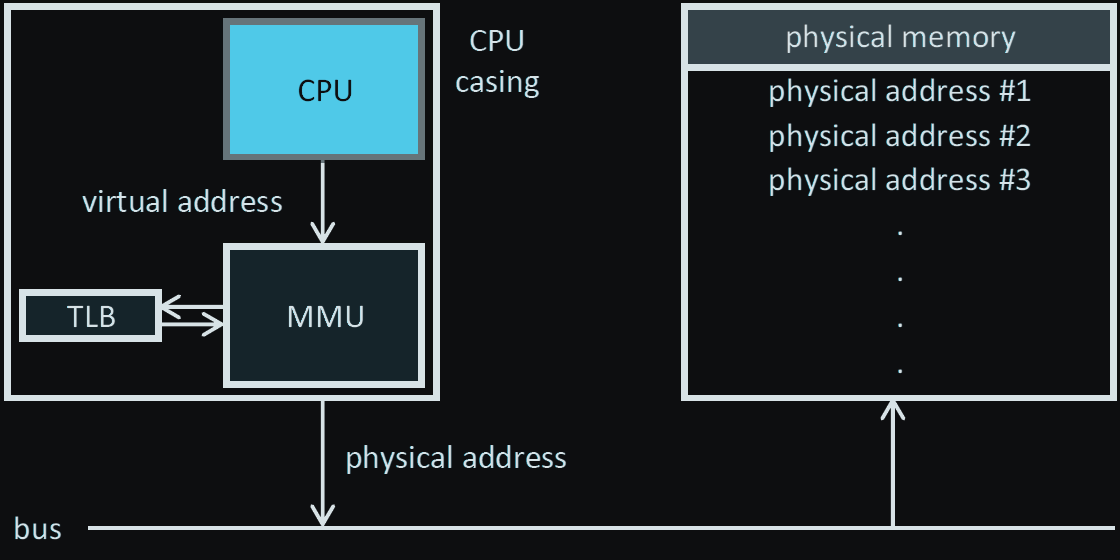
The translated physical address points to the location in system DRAM or VRAM where the data actually is. The NVIDIA CUDA Programming Guide explains that CUDA manages the placement and movement of data among these several physical memories.
Placement and Migration
A managed allocation is a memory region created with cudaMallocManaged. The CUDA Runtime and driver manage where this region is stored, when it moves, and the mapping for each processing unit. cudaMalloc creates a device allocation, and the program requests cudaMemcpy when it exchanges data with the host.
The CUDA documentation keeps these three apart. Below is one case on a discrete GPU where the data that x points to moves from system DRAM to VRAM. The pointer x holds the virtual address V, and the value of *x is assumed to be 41.
| Term | What it refers to | Example following x |
|---|---|---|
| mapping | The address relation connecting a virtual page to a physical frame | Before the move, V is connected to frame A in system DRAM. After the move, on the GPU the same V is connected to frame B in VRAM. The pointer holds the same V before and after the move. |
| placement | Which physical memory the data is currently stored in | If 41 is in frame A of system DRAM, the placement is system DRAM. After the move, if it is in frame B, the placement is VRAM. |
| migration | Moving data to a different physical memory, changing its placement | The page holding 41 is copied from frame A in system DRAM to frame B in VRAM, and the GPU’s address connection is changed to frame B. |
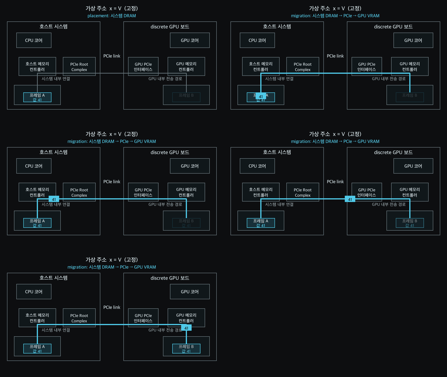
This figure is the discrete GPU path where CPU DRAM and VRAM are separated by PCIe. Placement is decided per page of a managed allocation, and the possible locations depend on the hardware structure.
| Where managed data can be placed | Moving to a separate VRAM | |
|---|---|---|
| discrete GPU | system DRAM or VRAM | yes |
| integrated GPU | shared system DRAM | accessed within the shared DRAM |
The value that must be read at an address is the result of the last write completed in the order set by synchronization. That result may be in a CPU or GPU cache, so before the next processing unit reads the same address, the access order and the cache state are aligned.
UVA and Unified Memory
CUDA’s UVA (Unified Virtual Addressing) places the CPU memory and each GPU memory of a process in one virtual address space. The CPU and GPU each use the mappings that are valid for them. UVA provides the address scheme that tells the memories apart. The accessor of a cudaMalloc allocation is the GPU. Unified Memory manages the access and placement of managed allocations and lets the next processing unit read the result of a write whose order was set by CUDA synchronization.
Unified Memory and Managed Allocation
Unified Memory provides managed allocations that both CPU and GPU code can use. cudaMallocManaged is the basic Runtime API that creates this allocation.
int *x = nullptr;
cudaMallocManaged(&x, sizeof(*x));
It secures space of sizeof(*x) bytes and records the starting address in the pointer variable x. &x passes the address of the pointer variable x itself to the function, so that the function can write the starting address into x. This allocation is released with cudaFree(x).
The explicit-copy style keeps a CPU-side h_data, a GPU-side d_data, H2D, and D2H in the code. The managed style has the CPU and GPU use the single x, and the data movement is handled by the Runtime, driver, and hardware according to what the current system supports.
The GPU Modifying a Value the CPU Wrote
The code below is the basic form in which the CPU and GPU use the same managed allocation in turn. A kernel is a function that runs on the GPU, and a thread is the unit of work that runs that function. This code makes 42 because one GPU thread adds 1 to 41 once.
#include <cstdio>
#include <cuda_runtime.h>

__global__ void add_one(int *x) {
    *x += 1;
}

int main() {
    int *x = nullptr;
    cudaMallocManaged(&x, sizeof(*x));

    *x = 41;
    std::printf("before kernel: %d\n", *x);

    add_one<<<1, 1>>>(x);
    cudaDeviceSynchronize();

    std::printf("after kernel:  %d\n", *x);
    cudaFree(x);
}
__global__ declares a kernel. A block is a bundle of GPU threads placed together. <<<1, 1>>> places one thread in one block. Right after the kernel launch the CPU keeps executing the next code, so cudaDeviceSynchronize(), which waits until the GPU work has finished, is placed between the GPU write and the CPU read.
Synchronization and Cache Coherence
The example above has the CPU write 41, the GPU change it to 42, and then the CPU read that value. Two things are needed here. The CPU must read after the GPU work has finished, and when it does it must read 42, the result of the GPU write.
The first is synchronization. cudaDeviceSynchronize() makes the CPU thread wait until the GPU work submitted earlier has finished. So the CPU read starts after the GPU write has finished.
The second is cache coherence. To reduce DRAM accesses, the CPU and GPU keep recent data in their own caches. A cache brings data in units of cache lines, which are bundles of consecutive bytes. After the GPU writes 42 into its cache, the cache state is aligned so that the CPU’s next read obtains 42.
There are two ways to achieve this cache coherence. When hardware aligns the cache state between processors directly, it is hardware coherence. When the driver adjusts the address connections, data movement, and cache state at access and synchronization boundaries so that the next processing unit reads the result of the earlier one’s write, it is software coherence. Among these, the work of making a cache’s changed values visible to another processing unit, or of discarding an older cached copy, is called cache maintenance.
Synchronization decides when the CPU reads, and cache coherence decides which value is visible at that moment. Placement names the physical memory where the data lies. When several processing units modify the same location, synchronization sets the access order.
Unified Memory Support Models
CUDA divides the way managed allocations are accessed into a Full model and a Limited model. The criteria are when the GPU prepares the managed allocation and whether CPU access is allowed while the GPU is running.
Full model
concurrentManagedAccess is the device attribute that indicates whether the CPU and GPU can use a managed allocation at the same time. If this value is 1, it is the Full model. When the GPU accesses a virtual page, CUDA sets up the GPU mapping and, if needed, moves that data into a physical frame in GPU memory. The CPU and GPU can use different addresses of the same managed allocation at the same time.
Limited model
If concurrentManagedAccess=0, it is the Limited model. CUDA makes the managed memory usable by the GPU at the kernel launch boundary and reopens CPU access after synchronization.
| Item | Full model | Limited model |
|---|---|---|
cudaMallocManaged | available | available |
| When the GPU gains access to the data | When the GPU accesses a virtual page, CUDA handles the mapping or migration | At the kernel launch boundary, CUDA puts the managed allocation into a GPU-accessible state |
| CPU access to managed memory while the GPU runs | Different addresses can be accessed | The CPU accesses after synchronizing the GPU work |
| Managed allocation larger than the physical memory the GPU can use | Allocations larger than GPU memory are usable | Used within the physical memory capacity available to the GPU |
Jetson AGX Orin uses shared DRAM together with the Limited model. There are also systems where a discrete GPU with separate CPU DRAM and GPU VRAM operates in the Full model.
In the Full model, the data belonging to each virtual page of a managed allocation is usually placed in the memory of the processing unit that first read or wrote that virtual page. The CUDA documentation calls this First touch. The program can tell the driver a preferred location with cudaMemAdvise. This information is called a hint, and the driver uses it in later placement decisions.
The current support model is decided by the combination of the operating system and its core, the OS kernel (a different word from the GPU kernel above), the CUDA driver, the GPU, and the CPU–GPU connection structure. So the support values of the current environment are checked with cudaDeviceGetAttribute.
managedMemory tells whether managed allocations created by explicit request, such as cudaMallocManaged, are supported. The next three attributes are read in the order below.
- If
concurrentManagedAccessis0, it is theLimited model. - If that value is
1, it is theFull model, and whenpageableMemoryAccessis0only managed allocations created explicitly through the CUDA API use this model. - If both values are
1, system allocations such asmalloc,new, andmmapalso fall within Unified Memory. Only then ispageableMemoryAccessUsesHostPageTablesread.0is software coherence, the method in which the driver manages mappings and migration to achieve the cache coherence above.1is hardware coherence, in which the CPU and GPU use the same host page table and hardware aligns the cache state directly.
Page Fault and Migration on a Discrete GPU
The following is the case of handling a GPU page fault by migration in a software-coherent Full model where CPU DRAM and GPU memory are separate. Software coherence is the method in which the driver manages the address connections and data movement of the CPU and GPU.
In the initial state, the managed data is in a physical frame of CPU memory, and the CPU mapping points to that frame. When the GPU first reads the same virtual address, a page fault occurs and the memory access stops. The page fault is the signal to prepare the GPU mapping to be used for that virtual page.
There are two ways to handle the fault: migration and remote mapping. The figure below is the migration path. The operating-system memory manager, which manages page tables and physical frames, works with the CUDA driver to prepare a physical frame in GPU memory, move the data, and install the GPU mapping. Once the mapping is ready, the stopped GPU instruction resumes.
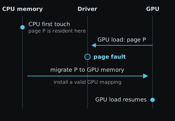
In the remote mapping path, the data is left in the physical frame of CPU memory and the GPU mapping is connected to that frame. Migration changes the data placement; remote mapping keeps it.
When the CPU and GPU modify the same pages in turn, page ping-pong can occur, where migration in both directions repeats. cudaMemPrefetchAsync moves the data of a given range in advance and brings the placement forward. CUDA synchronization sets the execution order of the CPU and GPU.
HMM
HMM (Heterogeneous Memory Management) is the Linux kernel subsystem that connects CPU page table changes, GPU faults, and page migration. In a Full model that uses HMM, system allocations made with malloc, new, and mmap can also be used by the GPU. Device attributes classify this support range, and running nvidia-smi, the command-line tool shipped with the NVIDIA driver, with -q shows whether HMM is currently in use in the Addressing Mode item.
Jetson AGX Orin: Shared DRAM and the Limited model
The concepts above were applied to an actual device. The environment is the Jetson AGX Orin Developer Kit, L4T (Linux for Tegra) R36.5.0, the Jetson Linux distribution, JetPack 6.2.2, which bundles the CUDA development tools, and CUDA 12.6. Tegra is the name of NVIDIA’s SoC product family that Orin belongs to. Orin is an SoC (System on Chip) that puts the CPU and GPU on one chip. Device 0 was an integrated GPU with compute capability 8.7. Compute capability indicates the generation of CUDA hardware features a GPU supports.
device=0 name=Orin cc=8.7 integrated=1
managedMemory=1
concurrentManagedAccess=0
pageableMemoryAccess=0
Verdict
managedMemory=1 means explicit managed allocations are supported, and concurrentManagedAccess=0 means the Limited model. pageableMemoryAccess=0 limits the scope of Unified Memory to explicit managed allocations such as cudaMallocManaged.
The device output above determines the Limited model. The NVIDIA Tegra memory model describes the shared SoC DRAM and cache behavior.
Shared DRAM and Cache
According to the Tegra documentation, the CPU and integrated GPU of Tegra share the SoC DRAM, and device memory, host memory, and unified memory are all allocated from the same physical SoC DRAM. The integrated=1 in the actual output also confirms the integrated structure of the Orin GPU.
Orin’s managed allocations are placed in the shared SoC DRAM. On top of the shared DRAM, the CPU and GPU can each store managed data in their own caches. The process of aligning the cache state so that the next processing unit reads the result of the earlier one’s write is cache coherence.
Orin’s one-way I/O coherency lets the GPU read values the CPU wrote into its cache. In the direction where the CPU reads values the GPU wrote, the CUDA driver manages the GPU cache state at synchronization boundaries.
The Tegra documentation explains that in an environment with concurrentManagedAccess=0, cache maintenance work is added to kernel launches and synchronization, and that this work can increase execution latency.
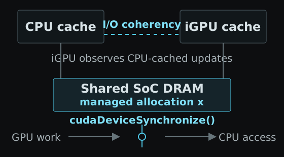
Building the example code above (managed_add.cu) for sm_87, the compile target for compute capability 8.7, and running it gave the following result.
before kernel: 41
after kernel:  42
The 41 → 42 in the output is the CPU reading 42, the result of the GPU write, after the GPU work finished. The device attributes recorded alongside show the Unified Memory support range of this Orin.
The full runnable code is in managed_add.cu, the attribute query code in orin_um_probe.cu, and the actual output in Orin observation.
References
- CUDA Programming Guide: Unified and System Memory: UVA, Unified Memory support models, device attributes, prefetch, HMM.
- CUDA Programming Guide: Unified Memory: detailed description of page faults, migration, coherence, and performance behavior.
- CUDA for Tegra: Memory Management: Tegra’s shared SoC DRAM, cache coherence, and
Limited modelguidance.